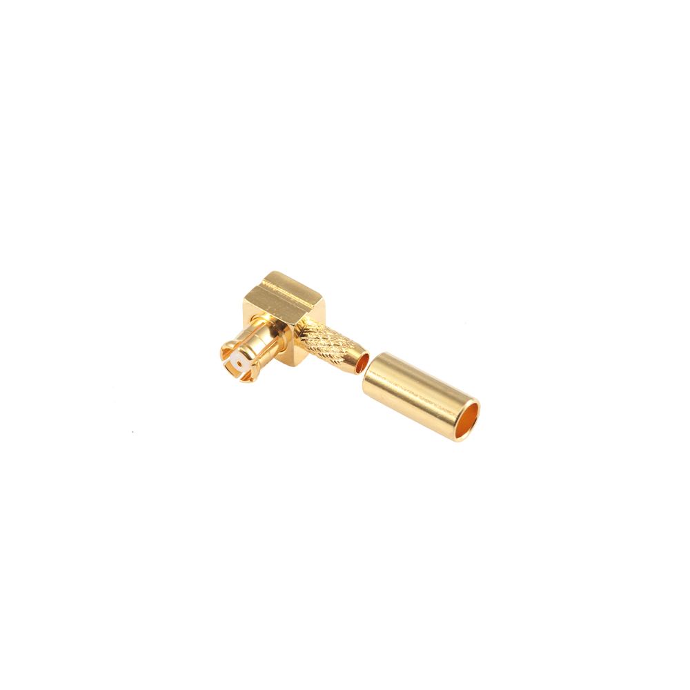
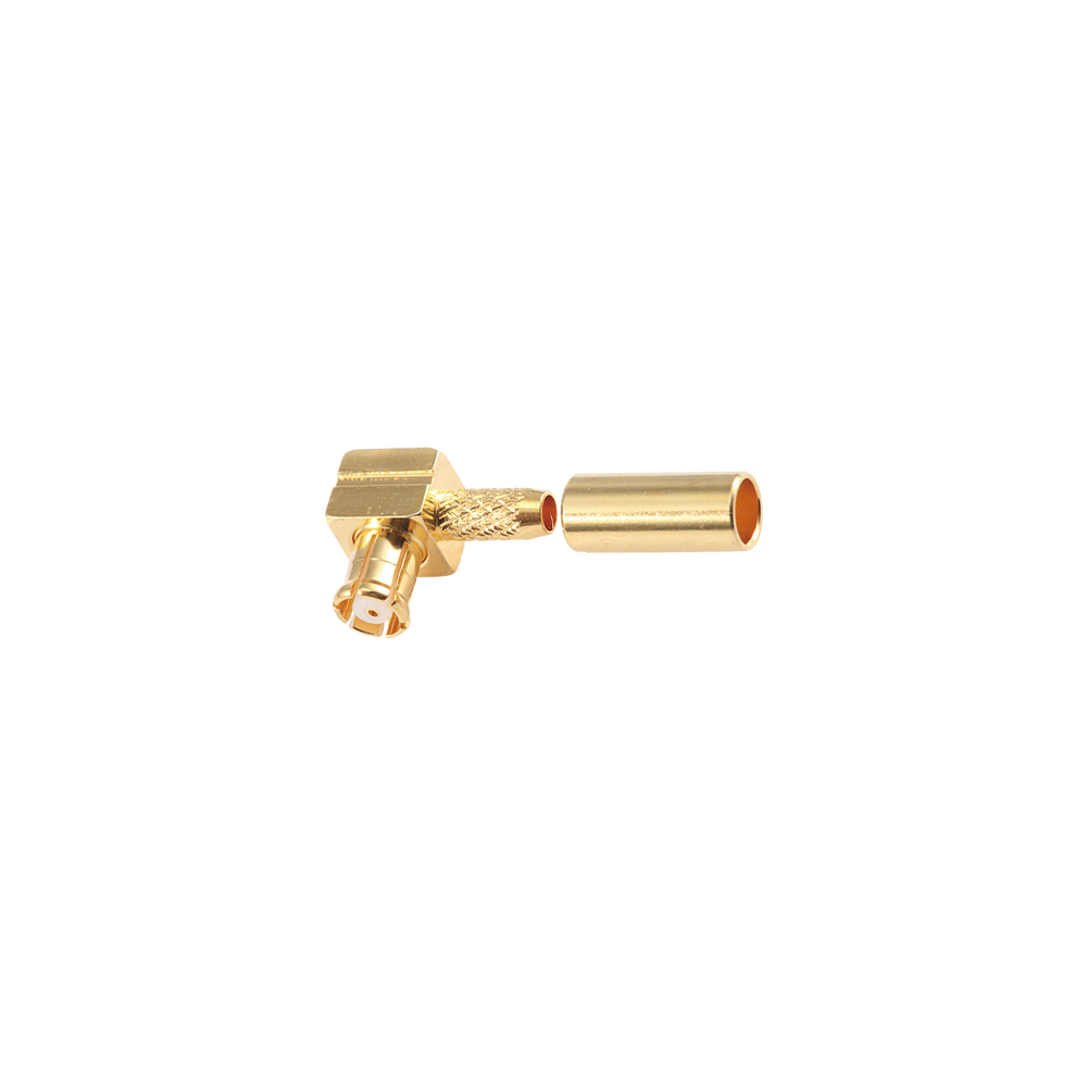
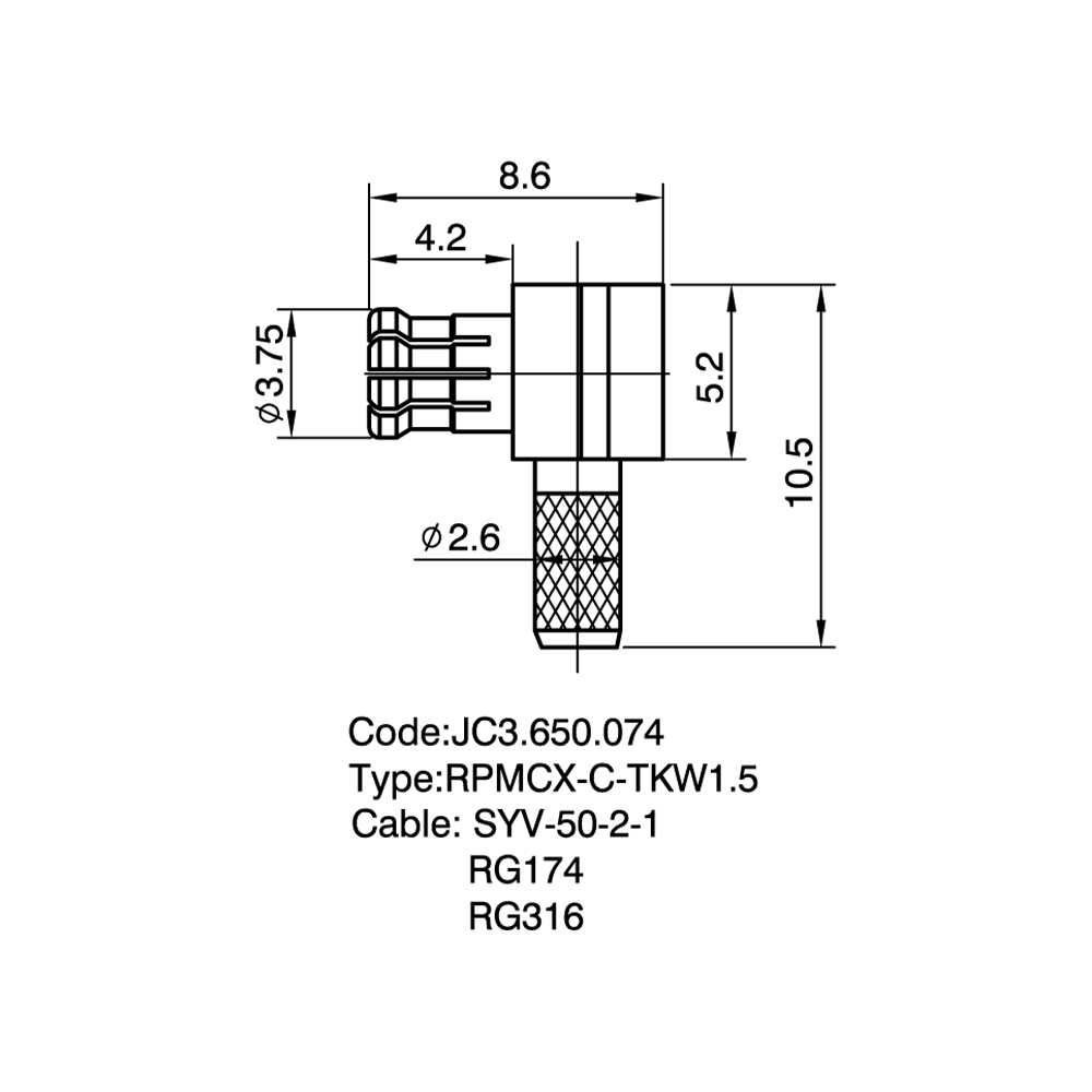
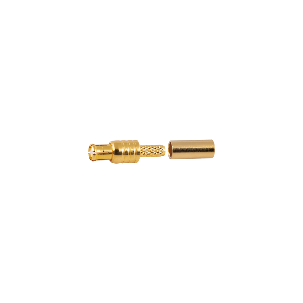
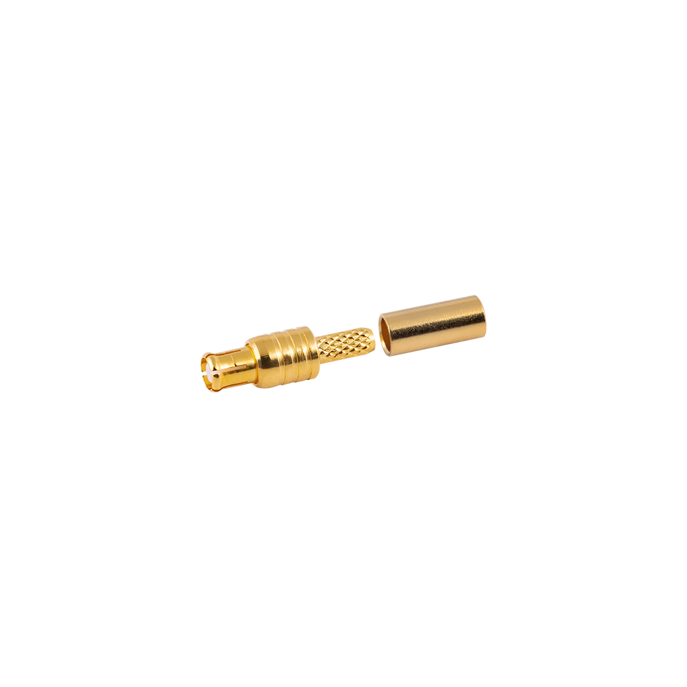
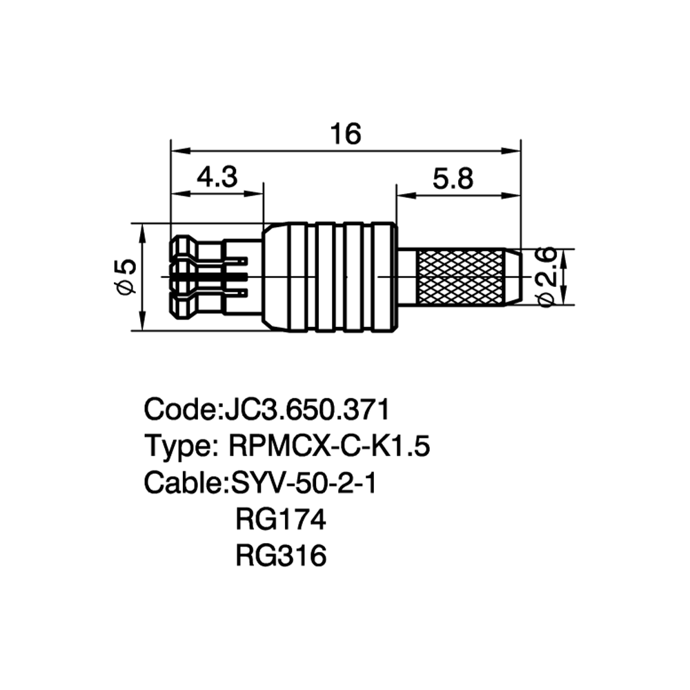
ที่ connector body—including the snap-on coupling mechanism and external housing—remains identical to the standard MCX version. This means that the external appearance of an RPMCX connector is indistinguishable from a standard MCX connector of the same body gender, and visual identification requires inspection of the centre contact rather than the connector shell[reference:11]. The snap-on coupling mechanism provides a secure retention force, with an engagement force of 20 N maximum and a disengagement force of 10 N minimum, ensuring reliable connection integrity under normal handling and environmental conditions[reference:12].
ที่ deliberate mismatch of centre contact gender relative to the connector body serves two primary purposes: regulatory compliance and functional prevention of mismating with standard polarity equipment. The reversed centre contact ensures that users cannot inadvertently connect a standard MCX antenna to an RPMCX device, which could potentially damage the device or degrade performance[reference:13]. This interface segregation is particularly important in compact wireless modules and IoT radio boards where antenna replacement by end users could compromise regulatory compliance.
ที่ following illustration provides a visual reference for the polarity convention of RPMCX connectors. The diagram shows that while the external body—including the snap-on coupling mechanism—remains identical between standard MCX and RPMCX versions of the same gender, the centre contact is reversed. This reversal is the defining characteristic of ขั้วต่อขั้วกลับ RPMCXs และเป็นกลไกป้องกันการจับคู่กับอุปกรณ์ MCX มาตรฐาน
ที่ diagram above illustrates the polarity convention for standard MCX and RPMCX connectors. In standard polarity MCX connectors, the male has a centre pin and the female has a centre socket. In RPMCX connectors, the male (plug) has a centre socket and the female (jack) has a centre pin. The external snap-on body—including the coupling mechanism—remains identical between standard MCX and RPMCX versions of the same gender. This reversal of the centre contact is what defines the RPMCX interface and is the mechanism by which these connectors prevent mismating with standard MCX equipment. The diagram also highlights that the terms "male" and "female" in RPMCX connectors refer to the connector body, not the centre contact, which is the source of much of the confusion surrounding these connectors. When selecting an RPMCX connector, it is essential to verify both the body gender and the centre contact configuration to ensure proper mating with the corresponding equipment. Clear polarity marking on RPMCX connector products facilitates accurate identification and selection, reducing the risk of incorrect ordering and installation.
ที่ electrical performance of ขั้วต่อขั้วกลับ RPMCXs ถูกกำหนดโดยพารามิเตอร์หลักหลายตัวที่ส่งผลโดยตรงต่อความสมบูรณ์ของสัญญาณในแอปพลิเคชัน RF และไร้สาย ขั้วต่อให้ประสิทธิภาพทางไฟฟ้าที่ทำซ้ำได้ตั้งแต่ DC ถึง 6 GHz[อ้างอิง:21] โดยมีอิมพีแดนซ์ลักษณะเฉพาะ 50Ω เป็นมาตรฐานสำหรับแอปพลิเคชันการสื่อสาร RF และไร้สาย[อ้างอิง:22]
ที่ maximum frequency of 6 GHz covers the majority of wireless communication bands, including GPS (L1/L2/L5), IoT (Sub-GHz, 2.4 GHz), Wi-Fi (2.4 GHz, 5 GHz), and emerging 6 GHz Wi-Fi 6E applications. The frequency range is cable-dependent; higher-performance cables can support operation up to the full 6 GHz specification[reference:23]. The voltage rating is 2255 VRMS maximum continuous, with a dielectric withstanding voltage of 1000 VRMS maximum[reference:24]. These ratings ensure that the connector can withstand the voltage levels encountered in typical RF and wireless applications without breakdown.
ที่ insertion loss is 0.10 dB maximum at 1 GHz[reference:25], which ensures that signal attenuation remains negligible, preserving receiver sensitivity and transmitter power. The power handling capability is 95 W maximum at 1 GHz at 25°C[reference:26], which is more than sufficient for the low-power wireless applications in which RPMCX connectors are typically deployed. The VSWR (return loss) is 1.3 maximum (-18 dB) from DC to 6 GHz[reference:27], indicating excellent impedance matching and minimal signal reflections.
ที่ insulation resistance is 10000 MΩ minimum[reference:28], and the centre contact resistance is 5 mΩ minimum[reference:29]. These low resistance values ensure that signal integrity is maintained and that power losses are minimised. The RF leakage is -60 dB maximum at 1 GHz[reference:30], indicating excellent shielding effectiveness that prevents signal leakage and reduces interference with nearby circuits.
ที่ following line chart presents typical insertion loss across the DC to 6 GHz frequency range for RPMCX connectors, demonstrating the flat response that ensures consistent signal quality across all operating frequencies.
ที่ line chart above shows the typical insertion loss of ขั้วต่อขั้วกลับ RPMCXs ข้ามช่วงความถี่ DC ถึง 6 GHz การสูญเสียการแทรกยังคงต่ำกว่า 0.05 dB ผ่านสเปกตรัมความถี่ส่วนใหญ่ โดยค่อยๆ เพิ่มขึ้นเป็นประมาณ 0.10 dB ที่ 6 GHz ระดับอ้างอิง 0.10 dB (เส้นประ) ระบุการสูญเสียการแทรกที่ระบุสูงสุดที่ 1 GHz [อ้างอิง: 31] การตอบสนองความถี่แบบคงที่นี้ช่วยให้มั่นใจได้ว่าการลดทอนสัญญาณยังคงสม่ำเสมอในทุกความถี่การทำงาน ซึ่งมีความสำคัญอย่างยิ่งสำหรับแอปพลิเคชันไร้สายบรอดแบนด์ ค่าการสูญเสียการแทรกที่ต่ำช่วยให้แน่ใจว่าความไวของตัวรับสัญญาณยังคงอยู่ และกำลังส่งไปถึงเสาอากาศโดยมีการลดทอนน้อยที่สุด VSWR (ไม่แสดงเป็นภาพกราฟิก) ยังคงต่ำกว่า 1.3:1 ทั่วทั้งย่านความถี่[อ้างอิง:32] ซึ่งแปลเป็นการสูญเสียย้อนกลับที่ดีกว่า 18 dB และบ่งชี้ถึงการจับคู่อิมพีแดนซ์ที่ดีเยี่ยม ความเสถียรของอิมพีแดนซ์นี้เกิดขึ้นได้จากการตัดเฉือนตัวเครื่องทองเหลืองและหน้าสัมผัสเคลือบทองอย่างแม่นยำ[อ้างอิง:33][อ้างอิง:34] ซึ่งช่วยให้มั่นใจถึงประสิทธิภาพทางไฟฟ้าที่สม่ำเสมอตลอดอายุการใช้งานของตัวเชื่อมต่อที่ 500 รอบการผสมพันธุ์ขั้นต่ำ[อ้างอิง:35] การรวมกันของการสูญเสียการแทรกต่ำ VSWR ที่ยอดเยี่ยม และการจัดการพลังงานสูง (95 W ที่ 1 GHz) [อ้างอิง: 36] ทำให้ตัวเชื่อมต่อ RPMCX เหมาะสำหรับแอปพลิเคชัน RF และไร้สายที่หลากหลาย ซึ่งความสมบูรณ์ของสัญญาณเป็นสิ่งสำคัญยิ่ง
ที่ reduced footprint of RPMCX connectors allows designers to place more functionality into smaller enclosures, which is particularly important for portable and embedded RF devices such as IoT modules, wearable electronics, and GPS receivers[reference:38]. The compact size also enables the use of multiple connectors on a single PCB without consuming excessive board area, which is beneficial for multi-band and MIMO wireless systems. The snap-on coupling mechanism further contributes to space efficiency by eliminating the need for the additional clearance required for wrench access in threaded connectors.
ที่ following bar chart compares the relative size of RPMCX connectors with other common connector types, demonstrating the space-saving advantages of the MCX interface family.
ที่ bar chart above illustrates the relative size of RPMCX connectors compared to SMA and SMB connectors. SMA connectors, commonly used in test equipment and higher-power applications, are the largest of the three types shown. SMB connectors are approximately 70% of the size of SMA connectors, offering a moderate reduction in footprint. RPMCX connectors are approximately 50% of the size of SMA connectors and 30% smaller than SMB connectors[reference:40]. This size advantage is achieved through the miniature MCX interface design, which reduces the outer conductor diameter and overall connector length. The compact footprint of RPMCX connectors enables denser PCB layouts and smaller device enclosures, which is particularly beneficial for portable and embedded applications. The size reduction does not compromise electrical performance; RPMCX connectors maintain the same 50Ω impedance and DC to 6 GHz frequency range as their larger counterparts. The snap-on coupling mechanism further contributes to space efficiency by eliminating the need for the additional clearance required for wrench access in threaded connectors. This combination of small size, reliable electrical performance, and fast snap-on mating makes RPMCX connectors a preferred choice for compact wireless devices where board space is at a premium.
ที่ difference lies in the centre contact gender. In standard MCX, a male connector has a centre pin and a female connector has a centre socket. In RPMCX, a male plug has a centre socket and a female jack has a centre pin. All other mechanical and electrical characteristics—including the snap-on coupling, 50Ω impedance, and DC to 6 GHz frequency range—remain identical[reference:68].